
For our initial visit to the Chelsea 145.450 repeater site:
I plan to document the duplexer configuration and its connectivity to the repeater. This means drawing up a diagram illustrating the duplexer cavities and their interconnectivity. Each cable will have a physical label attached to it and its length measured.
I then plan to test the repeater desensitization with a simple test described here. Jim and I are going to need someone to help us with this. This third person will need to position him or herself at a point distant, but dependably workable, to the repeater. This will be a “weak signal” station for the desensitization test.
I will have a test procedure written up to follow, but here is the informal plan. Find below a rough outline for what testing is planned although a detailed step-by-step test plan will be followed.
First Thing to Do
- Make a sketch of the repeater physical configuration.
- Show cable
- Interconnectivity
- cavity-to-cavity
- RX to cavity
- TX to cavity
- Duplexer to antenna
- Label each cable
- Confirm that each cable is of a double-shield type.
- document each length
- Interconnectivity
- The above was accomplished in April of 2023. Configuration is shown here.
A. Measure Tx Port Power
- Confirm at the repeater output power is set to MID LEVEL.
- Measure the TX output power (W) at the repeater TX port.
- Convert to dBm: Power dBm = 20.log10(PTX/0.001W)
- Measure the output power (W) at the duplexer antenna port
- Convert to dBm: Power dBm = 20.log10(PDuplexer/0.001W)
- Restore the repeater configuration to its operational status.
- One of these tests was accomplished on April of 2023 and is shown here.
B. Find the Carrier to Noise Delta
Any signals coming out of the repeater’s TX port must be blocked from entering the RX port where desensitization will occur. All of that energy is directed to the antenna. Any portion of that which finds its way back to the repeater’s RX port will cause desensitization. We know the carrier level from the TX measurement above.
- Confirm that the repeater configuration is operational.
- Connect the duplexer TX port to a variable attenuator.
- Connect the other end of the variable attenuator to a vector network analyzer RF input port.
- Record in dBm the noise level observed.
C. Measure the Receiver Input Impedance
A receiver’s input impedance is typically specified as simply 50 Ohms. However, each receiver’s antenna input (or RX input) will have a tolerance to that value and consequently will only be roughly 50 Ohms. For optimal repeater performance, it is necessary to know what the repeater’s RX input impedance is. Thus, it must be measured. But make sure to measure the RX input impedance using the duplexer cable that is used to connect the duplexer to that port.
D. Measure the Antenna Vector Impedance
For this measurement use an antenna analyzer such as the RigExpert AA-600.
E. Measure the Transmitter Impedance
An antenna with an impedance other than 50 Ohms can detune the cavities.
- Obtain the output power out of the TX port which was measured above.
- Reconnect the duplexer cable TX port to the duplexer for a fully operational repeater.
- Connect the RX port to a 50 Ohm dummy load.
- Measure the output power at the duplexer antenna port.
- Obtain the manufacturer’s insertion loss spec for the duplexer. Use this to determine what the output power should be.
- If the insertion loss is unknown, measure the S21 mode spec with the VNA.
F. Receive Desensitizaiton Test
This will guarantee that the transmit cavities are providing sufficient attenuation such that the noise generated by the TX port will not find its way into the RX port. While explained in detail in the link above, a rudimentary discussion is here.
For this test, we disable the transmitter and adjust the squelch so that it is open letting ambient signals come in. We then enable the transmitter at its normal power. If the audio out changes, it means leakage of TX into RX. It could be that adjusting the cavity is required but it is also possible that there is RF leaking from the cavity coax cabling.
Equipment Required

An RF power meter such as that shown is required.
Record the ambient temperature and log.
Testing #1–Measure Power into a dummy load through the duplexer.
- Task: Measure the repeater power out into a dummy load through the duplexer using all of the duplexer double-shield cables.
- Through this entire process, all of the duplexer cables will be used.
- The repeater is in a fully operational configuration.
- Confirm TX power is set to MEDIUM.
- Shut off power to the repeater.
- Disconnect the antenna feedline at the duplexer antenna feed.
- The feedline leading to the antenna is now dangling, not connected to anything.
- Prepare to connect the RF power meter and dummy load to the duplexer antenna feed.
- Connect the RF power measurement instrument to the duplexer antenna feed where the antenna feedline had connected to.
- Connect a dummy load to the RF power instrument output.
- The repeater configuration is now as fully operational except that it is configured to measure the power delivered into a dummy load through the duplexer rather than the antenna.
- Restore power to the repeater
- Measure the power delivered to the dummy load attached to the duplexer antenna feed.
- Remove power from the repeater.
- Disconnect the dummy load and reconnect the water tower antenna.
- The repeater configuration is now fully operational.
- I now have the standard established to gauge any changes made to the repeater.
Testing #2–Measure repeater TX port output power into a dummy load. The duplexer and antenna are not to be energized.
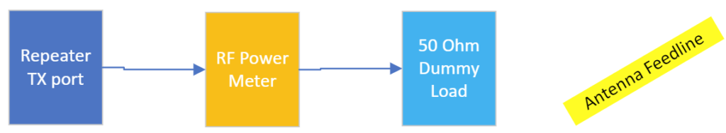
- Task: Measure the repeater TX port output power into a dummy load. The duplexer and antenna are excluded from this test.
- The repeater is in a fully operational configuration.
- Shut off power to the repeater.
- Disconnect the duplexer coax at the repeater TX port. The coax remains connected to the duplexer.
- The coax leading to the duplexer TX port is now dangling, not connected to anything.
- Task: Attach the RF power meter and dummy load to the repeater TX port.
- Connect the RF power meter to the repeater TX port.
- Connect a dummy load to the RF power instrument output.
- The repeater configuration is now as fully operational except that it is configured to measure the power delivered into a dummy load rather than the duplexer and antenna.
- Restore power to the repeater
- Measure the forward power delivered to the dummy load.
- Remove power from the repeater.
- Disconnect the dummy load.
- Remove the RF power meter.
- Restore the connection of the repeater TX output port to the duplexer TX input port.
- The repeater configuration is now fully operational.
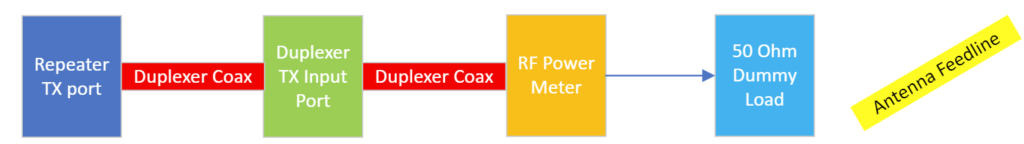
Testing #3–Measure repeater TX port output power through the duplexer and into a dummy load.

- Task: Measure the repeater TX port output power into a fully configured repeater system except that the duplexer is connected to a 50 Ohm dummy load. The repeater antenna is disconnected.
- The repeater is in a fully operational configuration.
- Shut off power to the repeater.
- Disconnect antenna feedline from the duplexer TX port.
- The antenna feedline is now dangling, not connected to anything.
- Task: Attach the RF power meter to the duplexer antenna connection and the dummy load to the RF power meter output.
- Connect the RF power meter to the duplexer antenna port.
- Connect the dummy load to the RF power instrument output.
- The repeater configuration is now as fully operational except that it is configured to measure the power delivered into a dummy load through the duplexer rather than the antenna.
- Restore power to the repeater
- Confirm power is set to MEDIUM.
- Measure the power delivered to the dummy load.
- Remove power from the repeater.
- Disconnect the dummy load and RF power meter.
- Restore the connection of the duplexer antenna port to the antenna.
- The repeater configuration is now fully operational once again.
Testing #4–Measure repeater TX port output power through the duplexer and into the repeater’s antenna on top of the water tower.

- Task: Measure the repeater TX port output power into a fully configured repeater system including the repeater’s antenna.
- The repeater is in a fully operational configuration.
- Shut off power to the repeater.
- Disconnect the duplexer coax from the repeater TX port.
- In its place, insert the RF power meter connecting its input to the TX port of the repeater and its output to the coax leading to the duplexer TX input.
- The repeater is now fully operational except that the RF power meter is positioned between the duplexer and the repeater TX port.
- Restore power to the repeater.
- Confirm that the repeater is still set for MEDIUM power.
- Measure the forward power out.
- Remove power from the repeater.
- Remove the RF power meter from the configuration reconnecting the duplexer to the repeater TX port.
- The repeater is now in its fully operational condition.
- Restore power to the repeater.
Testing #5–Measure the repeater output power as seen going into the antenna through the duplexer.

- Task: Measure the repeater output power into a fully configured repeater system including the repeater’s antenna as seen going into the antenna. This is the same as the test above except that the RF power meter has been moved.
- The repeater is in a fully operational configuration.
- Shut off power to the repeater.
- Disconnect the antenna feedline from the duplexer.
- In its place, insert the RF power meter connecting its input to the duplexer TX port and the other to the antenna feedline.
- The repeater is now fully operational except that the RF power meter is positioned between the duplexer and the repeater TX port.
- Restore power to the repeater.
- Confirm that the repeater is still set for MEDIUM power.
- Measure the forward power out.
- Remove power from the repeater.
- Remove the RF power meter from the configuration reconnecting the duplexer to the repeater TX port.
- The repeater is now in its fully operational condition.
- Restore power to the repeater.
Testing #6 — Measurement of all the cables.
- Make a sketch of the repeater configuration.
- List the labeling on the sketch that you see on the duplexer cans.
- Where does the repeater TX port connect to.
- Where does the repeater RX port connect to.
- Apply labels to each cable and make appropriate notations on the sketch.
- One-by-one, remove each cable and measure its length to a tolerance of +/- 0.1 cm.
- Before removing the next cable, reattach the earlier cable.
- Repeat the testing from Testing #1 above to verify that the repeater is fully operational with no new losses introduced.
Testing #7 — Test for the noise floor
In this test we will either use the repeater itself or a VHF receiver capable of receiving on 144.85 MHz brought in for the test. If the VHF receiver is being used, simply substitute the VHF receiver where the repeater is called for.
- From the repeater receive specifications, note the minimum voltage level it is able to receive. In the case of the Yaesu DR-2X, it is specified to detect signals as low as 0.2uV.
- Remove power from the repeater.
- Obtain an RF signal splitter/combiner
- A Wilkinson power splitter/divider
- A commercially available device such as this.
- Obtain an RF signal generator such as this one.
- Using the power combiner, connect its output to the repeater’s RX port.
- Connect the RX duplexer cable to one of the two power combiner input ports.
- With its power off, connect the RF signal generator to the other input of the power combiner.
- Insert sufficient attenuation between the RX port and the combiner such that you are able to dial in an RF signal at 144.85 MHz having a level as low as maybe -160dBw.
- Make a notation on what level of attenuation is being used.
- Restore power to the “repeater” and set its receive squelch such that you are able to hear static or noise coming out of the receiver.
- Make a note of the S-meter reading on the repeater receiver meter.
- Begin ramping up the voltage level to the RX port until you see the S-meter begin to respond to it.
- Record the RMS voltage level out that the RF signal generator says it is producing.
- Measure that voltage out with a high-impedance DMM leaving it connected to the signal combiner.
- Make the same measurement but with the RF signal generator output disconnected from its attenuation.
- If the two measurements are different, it means that loading is affecting the reading and determine what an accurate measurement value is.
- Mathematically determine what the voltage level is appearing at the RX port after applying the dB attenuation it facilitates.
- Compare this voltage measurement with the specifications for the receiver.
- If this voltage is less than what the receiver is specified to receiver, a preamp will likely be beneficial.
- If this voltage is greater than what the receiver is specified to receiver, a preamp is likely a waste of time and resources.
Time Permitting:
I would then like to insert a preamp at the repeater signal-in input if the above testing recommended it and if we have already purchased one.
For this operation, we will need one or two volunteers who have stationed themselves at pre-arranged locations which are at the repeater’s known periphery.